Modeling and Simulation of a Quadcopter
November 2024 - December 2024
Introduction
My fourth major course at USNA was EW301 (System Modeling and Simulation). We learned the fundamentals of developing, simulating, and validating models for dynamic systems.
The final project for this course was to research a technical paper from an academic journal or conference proceeding and create a figure from the paper.
Final Report
Abstract — Flying robots such as quadcopters can perform many tasks efficiently and safely across a variety of industries such as agriculture, construction, photography, the military, and more. With current advances in sensor, actuator, and energy storage technology, quadcopters can operate on a larger scale and tackle increasingly complex challenges. As a result, it is vital to understand how to model and simulate these complex systems for development purposes. The paper studied provides a way of modeling and simulating the movement of quadcopters with PD control. The following report delves into further analysis of the underlying modeling equations and utilizes a Euler’s method scheme to compose a simulation capable of reproducing the results found in the paper studied.
Introduction
Unmanned Aerial Vehicles, or UAVs, are robots that have the ability to fly. This gives them an upper hand over land-based robots as UAVs are capable of navigating around difficult terrain and move at faster speeds. As a result, these systems have proven to be effective at aiding a variety of industries. Some examples include infrastructure inspections, exploring dangerous regions, spraying crops, and more. With the current advancements in electronic technology and control theory, UAVs have become relatively simple to manufacture at scale. Being able to model UAVs, such as quadcopters, is essential during the developmental process. With a model, simulations can evaluate the performance of different controller designs, minimizing the risk of damage to physical components.
In [1], the authors propose a nonlinear dynamic model of a quadcopter and simulate its performance via a PD controller. The equations of motion for the six degrees of freedom were provided, along with the parameters used in simulation. In the following report, a manual reconstruction of the referenced paper was conducted supplemented by an in-depth analysis on the equations of motion and the implementation of a custom Euler integration scheme. Additionally, the report offers criticism to the control design provided and explains why it lacks practical feasibility.
Problem Statement and Objectives
Quadcopters offer a complex modelling problem as they involve four motors connected to a rigid body with some means to move about 3D space. It is a classic underactuated system with only throttle, roll, pitch, and yaw inputs to maneuver throughout six degrees of freedom. It is up to the engineer to come up with some method of converting the individual speeds of each motor into a position and orientation of the quadcopter. A controller must then be designed to manipulate the four motor speeds to reach a desired state.
The paper studied documents a nonlinear mathematical model of a quadcopter with three translational () and three rotational () degrees of freedom (DOF). Euler angles are used to model rotation as they are more intuitive. However, they are prone to “gimbal lock” which loses one degree of freedom. This issue can be resolved by using quaternions, but doing so can be confusing for the reader as they live in 4-dimensional space. Additionally, the authors propose a PD controller to achieve altitude, roll, pitch, and yaw angle setpoints. Details on the applied simulation method were excluded from the paper, but plots of the 4 setpoint responses were provided along with the associated gain values.
Modeling
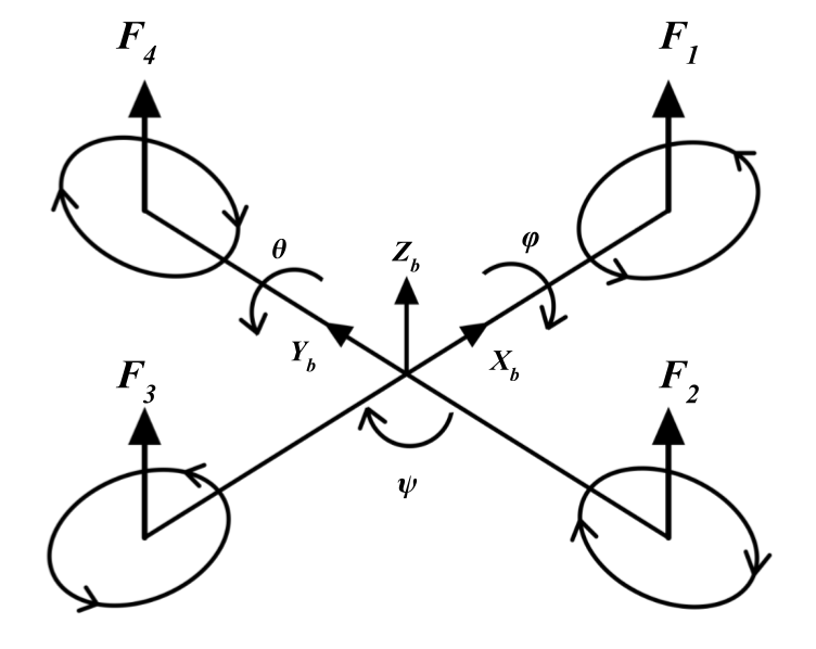
A quadcopter is defined as a multirotor with four motors, typically arranged in a “+” or “x” configuration. We decided to model the “+” variant of the quadcopter rather than the “x” variant as it is more intuitive. The front and back motors, and , rotate in the counterclockwise direction whereas the left and right motors, and , rotate in the clockwise direction as depicted in Figure 1. This configuration ensures that the torque due to the clockwise spinning motors counteract the torque due counterclockwise spinning motors.

Figure 1 Body Frame of Quadcopter
When modeling with Euler angles, it is crucial to maintain a standard rotation order as each rotation is relative to the new reference frame due to the previous rotation. For example, to yaw 90 degrees the quadcopter rotates 90 degrees about the original z axis. This establishes a new reference frame for the next rotation. Consequently, to roll 45 degrees, the quadcopter rotates 45 degrees about the new x axis. The new x axis due to the yaw rotation should not be confused with the original x axis before the yaw rotation. This paper will assume the order: yaw, pitch, roll.
Control of the quadcopter involves varying the speed of the motors. Rotating the motor, and thereby the propeller, generates two main forces: thrust (1) and torque (2).
Where is the thrust produced, is the torque, references the motor number, is the length between the motor and center of gravity, and is the angular velocity of the motor. The constants and are a simplified representation of the parameters affecting the thrust and torque produced by the propeller. This value can be estimated empirically and is influenced by factors such as air density and size of the propeller. Thrust will produce a lifting force as denoted in Figure 1 and torque will produce a moment in the direction opposite of the propeller rotation. Both of these phenomenon’s are derived from Newton’s third law which states, that every action has an equal and opposite reaction. The thrust generated by the propellers will push air down, causing the quadcopter to lift in the opposite direction. Additionally, the act of rotating a propeller clockwise will in turn apply a force to rotate the body counterclockwise.
In order to maneuver the quadcopter, there are four independent control inputs: throttle, roll, pitch, and yaw. To change the throttle, , all four motors are increased or decreased equivalently (3).
To make the quadcopter roll, , in the positive direction, keep and the same, but increase and decrease (4). To roll the opposite direction, decrease and increase .
To make the quadcopter pitch, , in the positive direction, keep and the same, but increase and decrease (5). To pitch in the opposite direction, decrease and increase .
To make the quadcopter yaw, , in the positive direction, increase both and , but decrease both and (6). To yaw in the opposite direction, decrease both and , but increase both and .
Equation (7) represents (3), (4), (5), and (6) in matrix form.
From a practical control perspective, it is more beneficial to calculate the resulting motor speeds based on the four control inputs (8).
With (7) and (8), understanding the relationship between motor speed and change in translation or rotation is straight forward. It is important to notice that the four control inputs , , , and affect movements relative to the body. These changes however, are not equal to the movements which are observed from a fixed point of view. This problem is exacerbated when attempting to integrate sensors such as a barometer and GPS. For example, when using these sensors to estimate altitude, a fixed reference frame is being used. Altitude is defined as the location along the z axis relative to Earth. However, if the quadcopter is pitched or rolled, the z axis relative to the body no longer aligns with the z axis relative to Earth. This can cause problems when trying to maintain altitude as maintaining position on the z axis relative to the body, will not always equate to maintaining altitude or position on the z axis relative to Earth. As a result, it is important to define two coordinate systems, one body frame and one Earth frame. The body frame is represented in Figure 1 where the reference frame is always fixed to the body of the quadcopter. No matter the orientation, the body frame’s z axis will always be orthogonal to the quadcopter’s body. Furthermore, the Earth frame is fixed, with the z axis orthogonal to the surface of the Earth.
Moving between the two coordinate systems can be achieved using a rotation matrix accounting for the three successive Euler angle rotations. Before the first rotation, the body frame and Earth frame are aligned. Sticking with the yaw, pitch, roll order convention, first rotate about the z axis (yaw) through an angle (9). The frame refers to the original Earth frame and refers to the rotated reference frame.
Next, pitch about the new y axis by the angle (10).
Finally, roll about the new x axis by the angle (11). The frame refers to the final body frame.
Equation (12) represents the derivation of the rotation matrix of the original Earth frame, , in the fully transformed body frame, .
Equation (13) is the expanded form of where represents and represents .
With a method of converting between both reference frames, deriving the translational equations of motions is straight forward. Newton’s 2nd law of motion states that the acceleration of an object is directly proportional to the net force acting on it and inversely proportional to its mass (14).
For simplification purposes, the model assumes no drag and claims that the gyroscopic effects due to the spinning motors are negligible. Therefore, the only forces acting on the body is the total thrust, , and gravity, (15). Notice how the accelerations , , and are in relation to the earth frame but is relative to the body frame. The transformation of to the earth frame is achieved by multiplying the rotation matrix .
Expanding (15) and isolating the linear accelerations , , and is illustrated in (16).
Deriving the rotational equations of motion is a little more difficult due to the fact that the time rate of change of Euler angles does not directly equate to angular velocity of the body frame. This makes sense because the yaw angle, applied first, is not rotated about the final body yaw axis. Instead, pitch and roll rotations have to be incorporated before calculating the time rate change for yaw relative to the final body frame. Equation (17) illustrates this concept in mathematical form.
The vector, , denotes the angular velocity of the body frame and , , and denote the instantaneous change of Euler angles. Notice how the time rate change vector for yaw, , is multiplied by the rotation matrices and to account for the roll and pitch rotations.
Equation (18) is the expanded form of (17).
It is more beneficial to calculate the time rate change of Euler angles from the angular velocity of the body frame (19). Numerically integrating , , will get the Euler rotation angles , , to be used in (16).
A method of calculating the angular velocity can be derived using Euler’s rotation equations. Equation (20) denotes the general vector form.
refers to the vector of the applied torques (21). , , and denote the torques about the x, y, and z axis. Notice how these torques also equate to , , and as defined in (4), (5), and (6).
refers to the principle inertia matrix where , , and denotes the moment of inertia about the x-axis, y-axis, and z-axis respectively (22).
denotes the angular velocity of the body frame, . denotes the angular acceleration of the body frame . Equation (23) represents (20) rearranged with the vectors plugged in.
Equation (24) is the result of simplifying and isolating , the angular velocity vector.
All equations required to model the quadcopter have been derived. Table 1 refers to the parameters used.
Table 1 Quadcopter Model Parameters
A PD controller was utilized for altitude, roll, pitch, and yaw angle control. A PD controller for altitude is plausible because the force of gravity on the quadcopter is known (25). and denote the proportional and derivative gains of the controller. refers to the altitude error.
Equations (26), (27), and (28) refer to the PD controllers for the roll, pitch, and yaw angles respectively. , , and denote the associated roll, pitch, and yaw errors.
Table 2 refers to the gains used.
Table 2 PD Gains
Notice the use of the derivative on measurement versus taking the derivative on error. This is implemented to eliminate derivative kick by assuming the setpoint is constant (29)
Simulations
Simulation of the quadcopter plant system can be accomplished using the equations of motion (16) and (24), with (19) serving as an equation to transform the angular velocities into the time rate change of the Euler angles. Numerical integration of variables , , , , , , , , , , , and is achieved using the Euler method (30). Where denotes the integrated variable and the variable to integrate. The step size, , was set to 0.001 seconds.
The feedback control system is simulated using the PD control equations (25), (26), (27), and (28). The derivative term is calculated by taking the backward difference (31). Where denotes the derivative of the variable . The sampling rate, , is equal to the step size of 0.001 seconds.
Results
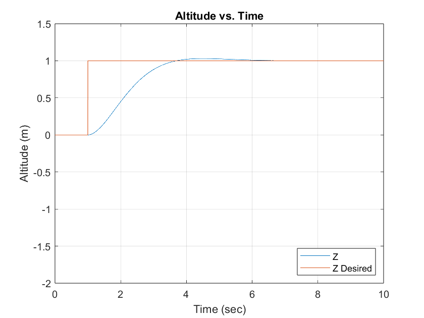
Figure 2 Simulated Altitude PD Response
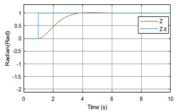
Figure 3 Paper Altitude PD Response [1]
Figure 2 illustrates the altitude step response of the simulated PD controller with a settling time of 2.510 seconds and percent overshoot of 2.9683%. Figure 3 illustrates the altitude plot provided from the paper that was emulated.
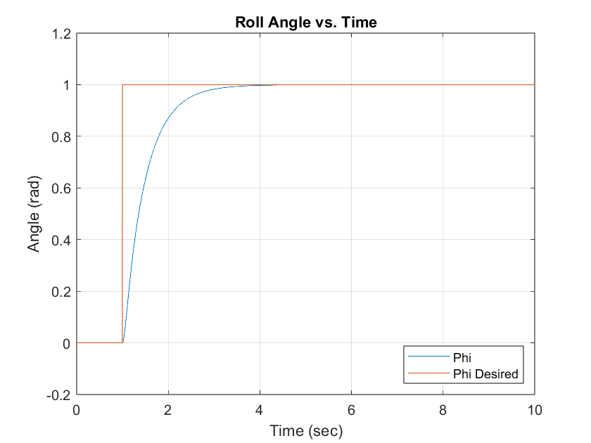
Figure 4 Simulated Roll Angle PD Response
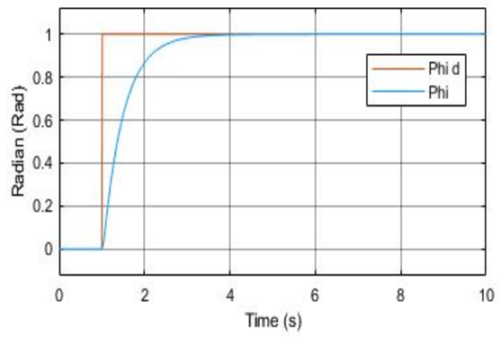
Figure 5 Paper Roll Angle PD Response [1]
Figure 4 illustrates the roll angle step response with a settling time of 1.933 seconds and negligible percent overshoot. Figure 5 illustrates the roll angle plot provided from the paper that was emulated.
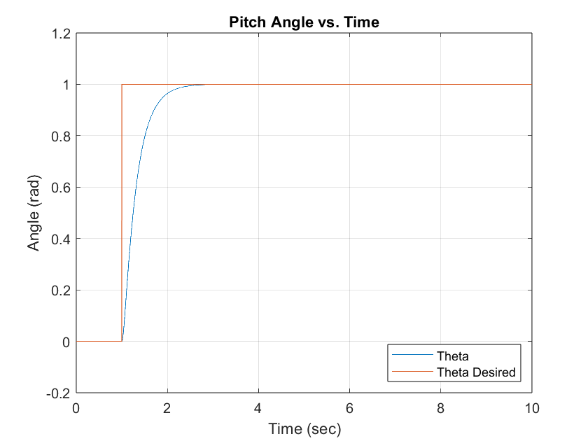
Figure 6 Simulated Pitch Angle PD Response
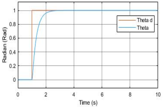
Figure 7 Paper Pitch Angle PD Response [1]
Figure 6 illustrates the pitch angle step response with a settling time of 1.166 seconds and percent overshoot of 0.0248%. Figure 7 illustrates the pitch angle plot provided from the paper that was emulated.
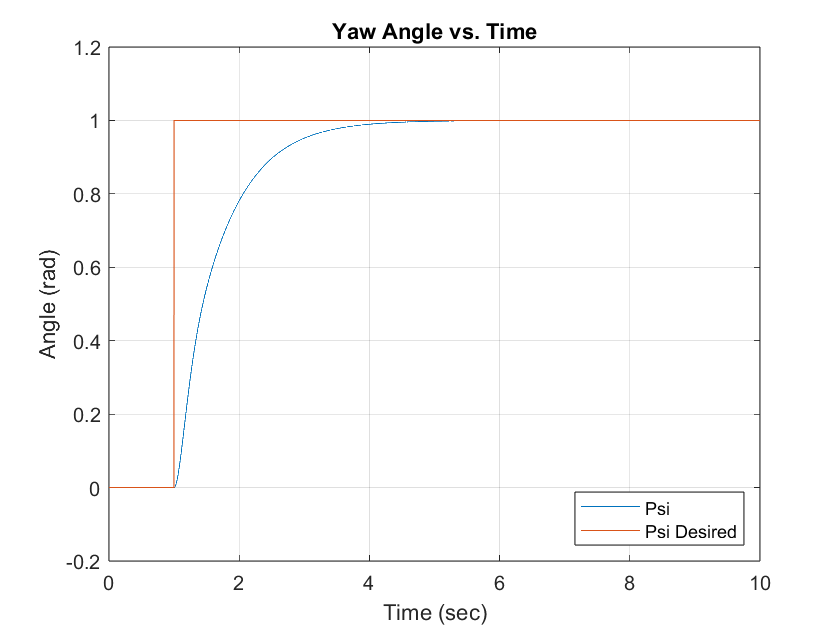
Figure 8 Simulated Yaw Angle PD Response
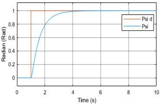
Figure 9 Paper Yaw Angle PD Response [1]
Figure 8 illustrates the yaw angle step response with a settling time of 2.576 seconds and negligible percent overshoot. Figure 9 illustrates the yaw angle plot provided from the paper that was emulated.
The paper did not provide the settling time or overshoot of the responses, but by visual inspection, both associated plots for altitude, roll, pitch, and yaw are identical. Additionally, while the article did not specify the simulation method used, the Euler method is a suitable approach for effectively modeling the quadcopter control system, as evidenced by similar results.
The use of a PD controller for altitude served as a means of testing the quadcopter model rather than a reasonable control approach. It is unrealistic to program a controller that will only work if the mass of the system is always known. A more practical solution would be a PID controller for . This allows in to be replaced by an integral term, which will gradually converge to the gravitational force over time.
Conclusion
The reproduction of the proposed quadcopter model in [1] was conducted with further analysis on the equations of motion and the implementation of a custom Euler integration scheme. The similarity of the setpoint responses for altitude, roll, pitch, and yaw angles indicate that the simulation was properly replicated. Furthermore, this report includes an analysis of both the transient and steady-state responses, which was not covered in the referenced paper. Future refinements could include the use of quaternions and the modeling of wind resistance effects. Nevertheless, the model produced in this report serves as a stepping stone for further developments, such as implementing a trajectory controller.
References
[1] Karahan, Mehmet, and Cosku Kasnakoglu. “Modeling and Simulation of Quadrotor UAV Using PID Controller.” Conference-processing. ECAI 2019 - International Conference – 11th Edition. IEEE, 2019.