Autonomous Search And Rescue Drone
July 2018 - August 2020
Story
Between 1992 and 2007, around 11 Search and Rescue (SAR) operations took place each day in the U.S. National Parks. Each costing about $895 per incident and totaling to $58, 572, 164. Furthermore, around 700 lives are lost per year from coast guard SAR missions. Better training and technological advancements have helped the decline in fatalities and costs, but it is still relatively expensive. Therefore, there is a need for a novel device that would minimize the fatality rate and costs of SAR operations.

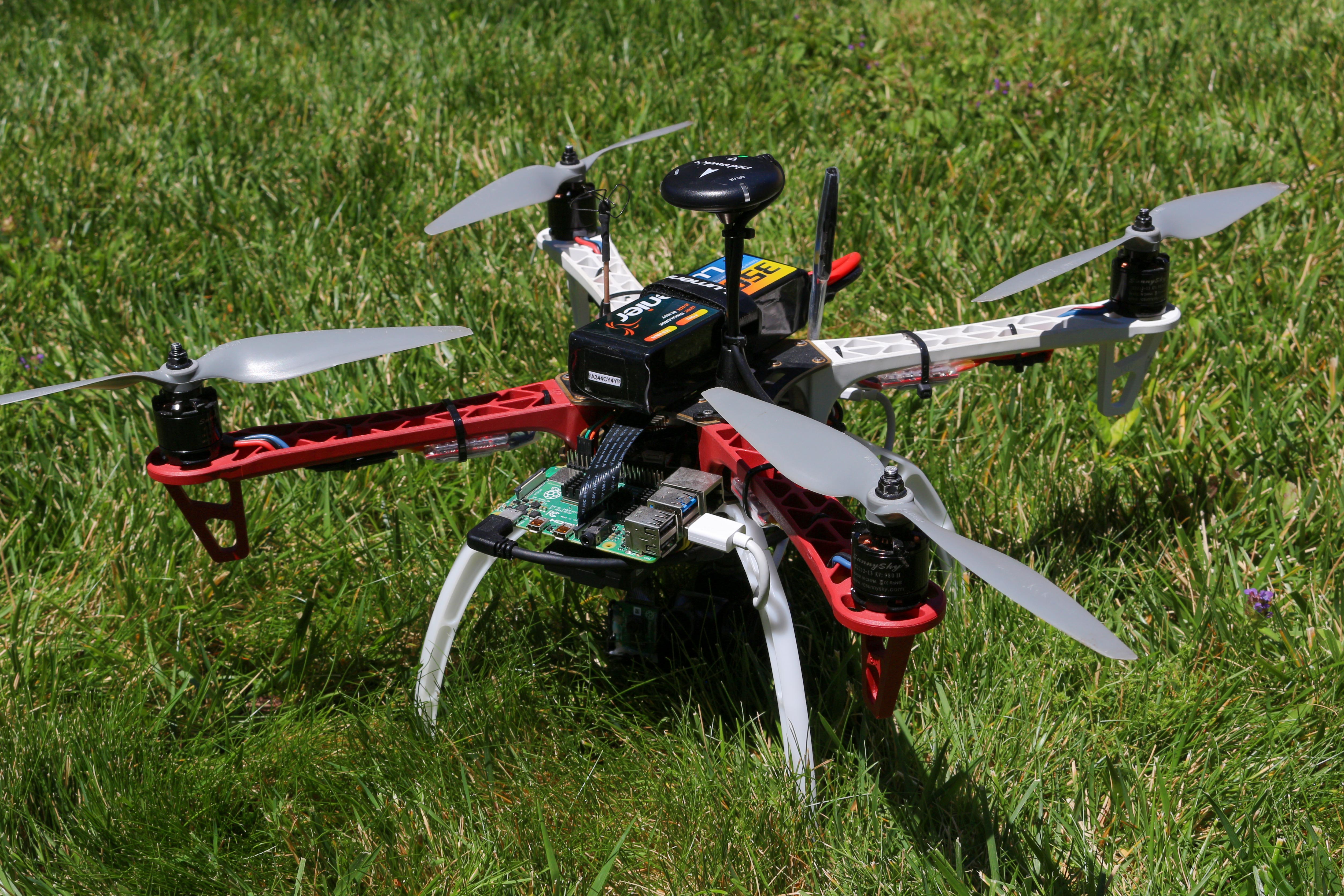
This device is a drone that can successfully fly autonomously over any terrain and search for missing subjects. The operator just has to plug in the battery, flip a switch, and will take off on a programmed SAR pattern configurable to any search area and pattern. A camera takes video of the ground below and feeds that input into a compute module to run a Convolutional Neural Network (CNN). This CNN is capable of detecting humans, cars, and several other objects that can provide clues for the SAR team to find the missing subject/s. When the drone detects a person, it will follow the subject if it moves and simultaneously send GPS coordinates with time stamps to the SAR team. The operator can also view the live video to coordinate how to reach the missing subject in the safest manner. When low on battery, the drone will autonomously fly back to where it took off. Utilizing a drone instead of having to use helicopters or land teams serves as a cheaper and safer way to perform SAR operations. Teams could use multiple of these drones and search a large area fast and autonomously.
Demo Video
Code
Please clone my GitHub repository to follow along with this tutorial.
Components List
Setting Up Your Raspberry Pi
In this tutorial, I used a Raspberry Pi 4 Model B 4GB. If you have the 8GB version, feel free to use it for better performance (you will get more fps enabling better tracking capabilities). However, I have never tested it with the 8GB version. This project does work with a Raspberry Pi 3 Model B+ but with slower fps.
If this is your first time using a Raspberry Pi, make sure set it up with the latest Raspberry Pi OS. Follow this tutorial for guidance. If you've used Raspberry Pi's in the past, make sure to flash your SD card with a fresh new RPI OS.
After booting up and getting everything set up, enter this into the terminal:
$ sudo raspi-config
Use the arrow keys to navigate to the Interface Options section and press enter.
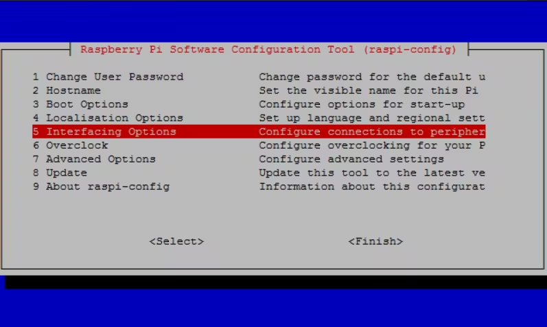
You will want to turn on the Camera, SSH, and Serial via this menu:
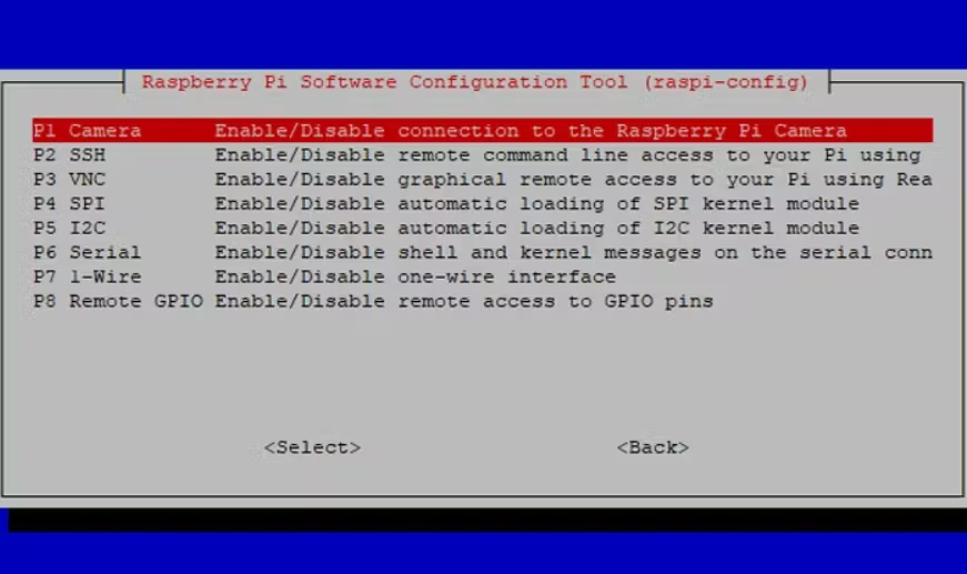
Once complete, you can exit and reboot.
Enabling the camera will allow us to perform the necessary computer vision in order to detect missing persons. SSH will allow you to remotely program and control the RPI via your laptop/PC without a wire connecting the two together. This is just for convenience and safety. The Serial will allow the RPI to communicate with our onboard flight controller via MAVLink.
Once the Camera, SSH, and Serial is enabled, you can now connect to the RPI via SSH.
First, find out your RPI's IP address by typing this into the RPI's terminal:
$ hostname -I
If your using a windows laptop/PC, then make sure you have OpenSSH Client installed. Go to Settings > Apps > Apps & Features > Optional Features > Search for OpenSSH Client in the text field, and choose to install OpenSSH Client if not installed already.
Then in your terminal (for either Linux or Windows users) type:
ssh pi@IP
Replace IP with the IP address of your RPI.
You will then be prompted for the password for the pi login. The default password on Raspberry Pi OS is raspberry.
Then, make sure your RPI is updated by using these two commands in your terminal:
$ sudo apt-get update
$ sudo apt-get upgrade
Setting Up Your Coral TPU
Now, we can start installing the necessary packages and programs to enable computer vision via the Google Coral Edge TPU USB Accelerator.
First, add the Coral Edge TPU package repository:
$ echo "deb https://packages.cloud.google.com/apt coral-edgetpu-stable main" | sudo tee /etc/apt/sources.list.d/coral-edgetpu.list
$ curl https://packages.cloud.google.com/apt/doc/apt-key.gpg | sudo apt-key add -
$ sudo apt-get update
Now, install the EdgeTPU runtime library:
$ sudo apt-get install libedgetpu1-std
Next, install the EdgeTPU Python API:
$ sudo apt-get install python3-edgetpu
Followed by a reboot to complete the installation process:
$ sudo reboot now
We will now set up a Python virtual environment to help isolate the python packages used in this tutorial. We will be using virtualenv and virtualenvwrapper.
First, install pip:
$ wget https://bootstrap.pypa.io/get-pip.py
$ sudo python get-pip.py
$ sudo python3 get-pip.py
$ sudo rm -rf ~/.cache/pip
Next, install virtualenv and virtualenvwrapper:
$ sudo pip install virtualenv virtualenvwrapper
After installing, edit the ~/.bashrc file:
$ sudo nano ~/.bashrc
Add the following lines to the bottom of the file:
# virtualenv and virtualenvwrapper
export WORKON_HOME=$HOME/.virtualenvs
export VIRTUALENVWRAPPER_PYTHON=/usr/bin/python3
source /usr/local/bin/virtualenvwrapper.sh
Save and exit using ctrl + x, y, enter.
Next, reload your ~/.bashrc file to apply our changes:
$ source ~/.bashrc
Finally, create our Python 3 virtual environment:
$ mkvirtualenv sar -p python3
From now on, always ensure your in the sar virtual environment. If your not, use this command:
$ workon sar
Now we need to create a sym-link to link our EdgeTPU runtime into our sar virtual environment.
Run this to find the path where the Python EdgeTPU package is installed:
$ dpkg -L python3-edgetpu
...
/usr/lib/python3
/usr/lib/python3/dist-packages
/usr/lib/python3/dist-packages/edgetpu
/usr/lib/python3/dist-packages/edgetpu/__init__.py
...
Notice the line /usr/lib/python3/dist-packages/edgetpu. This is our root directory of the edgetpu library.
Now, we can create the sym-link:
$ cd ~/.virtualenvs/sar/lib/python3.7/site-packages
$ ln -s /usr/lib/python3/dist-packages/edgetpu/ edgetpu
$ cd ~
To test our installation, open up a Python shell:
$ workon sar
$ python
>>> import edgetpu
>>> edgetpu.__version__
'2.12.2'
Finalize the setup process for our Coral TPU by installing python packages that will be needed to use our PiCamera and perform image processing:
$ pip install "picamera[array]" # Raspberry Pi only
$ pip install numpy
$ pip install opencv-contrib-python==4.1.0.25
$ pip install imutils
$ pip install scikit-image
$ pip install pillow
Now we can test the TPU on an example program.
First, install the example package:
$ sudo apt-get install edgetpu-examples
Then, add write permissions to the examples directory:
$ sudo chmod a+w /usr/share/edgetpu/examples
Change directories and run the test program:
$ cd /usr/share/edgetpu/examples
$ python classify_image.py \
--mode models/mobilenet_v2_1.0_224_inat_bird_quant_edgetpu.tflite \
--label models/inat_bird_labels.txt \
--image images/parrot.jpg
---------------------------
Ara macao (Scarlet Macaw)
Score :  0.61328125
---------------------------
Platycercus elegans (Crimson Rosella)
Score :  0.15234375
If you get a similar response as above, that means you did everything correct.
If you're curious, here is what parrot.jpg looks like:

Installing DroneKit
DroneKit allows us to utilize a companion computer (the RPI in our case) to control an ArduPilot based flight controller. In this tutorial, we are using the RPI and Google Coral TPU to perform object detection and simultaneously send commands to the PixHawk 4 flight controller to move our drone and find the missing persons.
First, make sure you have pip and python-dev installed:
$ sudo apt-get install python-pip python-dev
Next, install DroneKit:
$ workon sar
$ pip install dronekit
$ pip install dronekit-sitl
Now we test our installation with a simple program. First we need to clone the GitHub repository:
$ git clone https://github.com/bandofpv/Search-and-Rescue-Drone
Navigate to the Search-and-Rescue-Drone repository and run the test program:
$ cd Search-and-Rescue-Drone
$ python dronekit_test.py
If installed properly, you should get the following response:
Start simulator (SITL)
Downloading SITL from http://dronekit-assets.s3.amazonaws.com/sitl/copter/sitl-win-copter-3.3.tar.gz
Extracted.
Connecting to vehicle on: 'tcp:127.0.0.1:5760'
>>> APM:Copter V3.3 (d6053245)
>>> Frame: QUAD
>>> Calibrating barometer
>>> Initialising APM...
>>> barometer calibration complete
>>> GROUND START
Get some vehicle attribute values:
 GPS: GPSInfo:fix=3,num_sat=10
 Battery: Battery:voltage=12.587,current=0.0,level=100
 Last Heartbeat: 0.713999986649
 Is Armable?: False
 System status: STANDBY
 Mode: STABILIZE
Completed
Building The Drone
In this tutorial, I'm assuming you have a decent amount of experience in building drones, so I won't go into too much detail in terms of how I built mine as its relatively simple and self explanatory.
Motor and ESC placement are all standard. Here is a nice schematic illustrating how to wire up the Battery, Motors, and ESC's together onto the PDB:
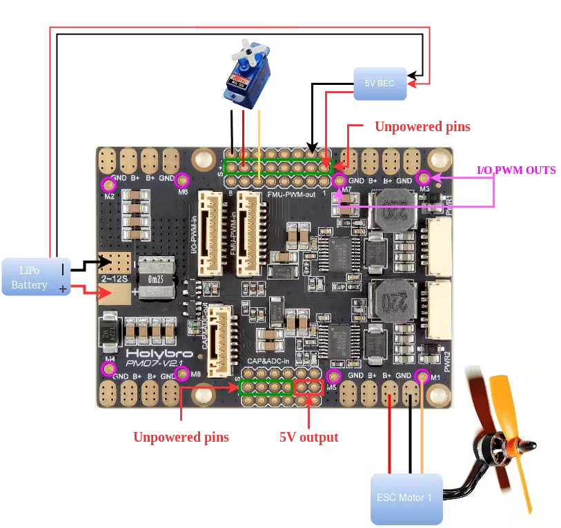
The PDB is mounted in the center of the frame (usually where the flight controller would go) because the PixHawk 4 can't fit inside:
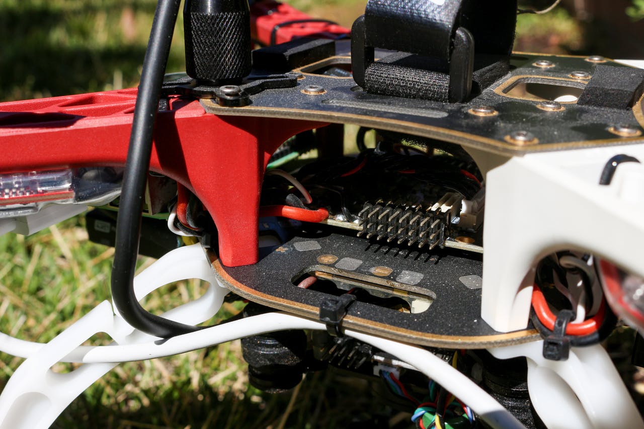
So the PixHawk 4 flight controller is mounted upside down on the bottom side of the bottom plate of the frame. Make sure to also use anti-vibration foam/gel to mount the flight controller to reduce vibration that can affect flight performance:
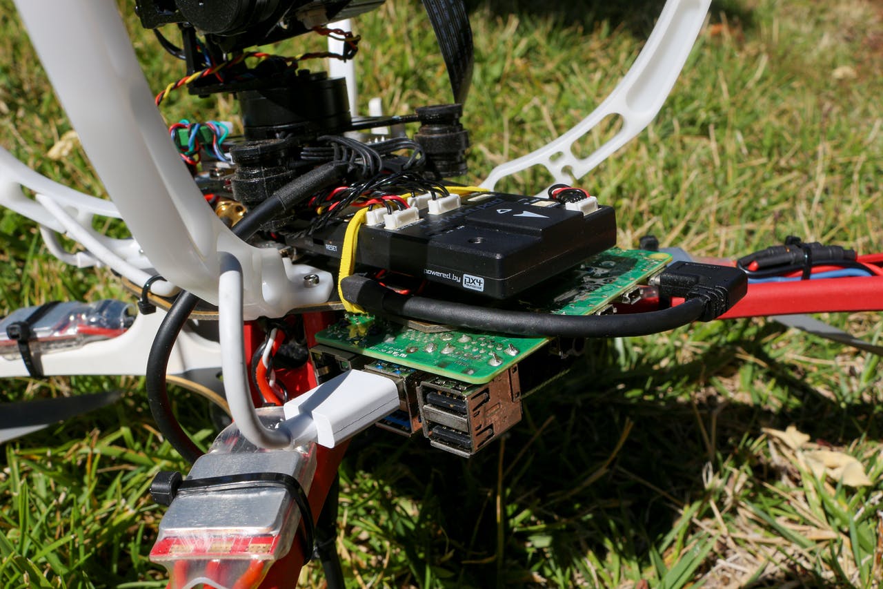
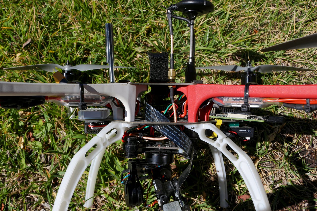
The gimbal is also mounted on the bottom side of the bottom plate on the frame, but I used metal standoffs to raise the gimbal off the bottom plate to give space for the flight controller. Both the FPV camera and the RPI The RX is also mounted on the bottom side of the bottom plate:
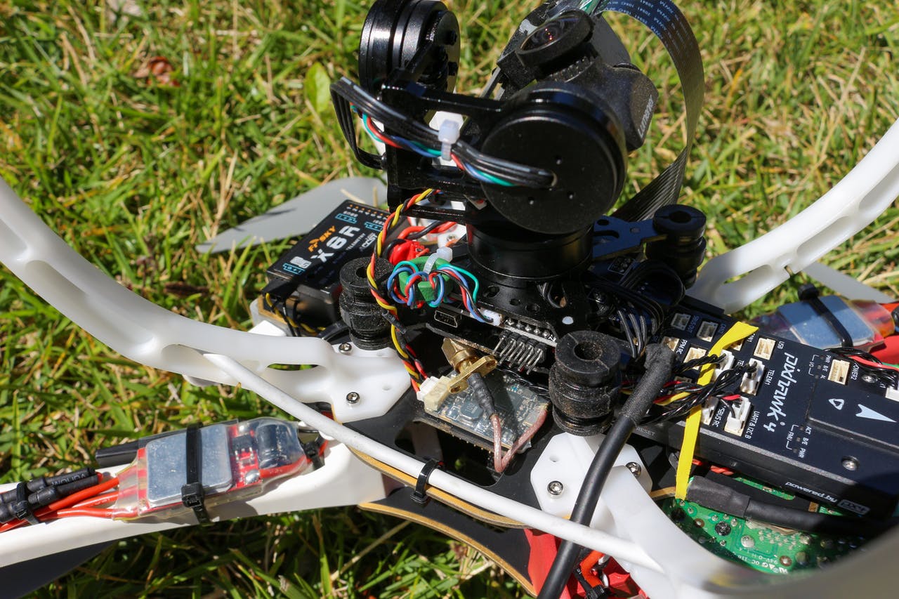
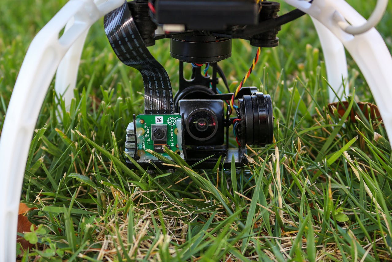
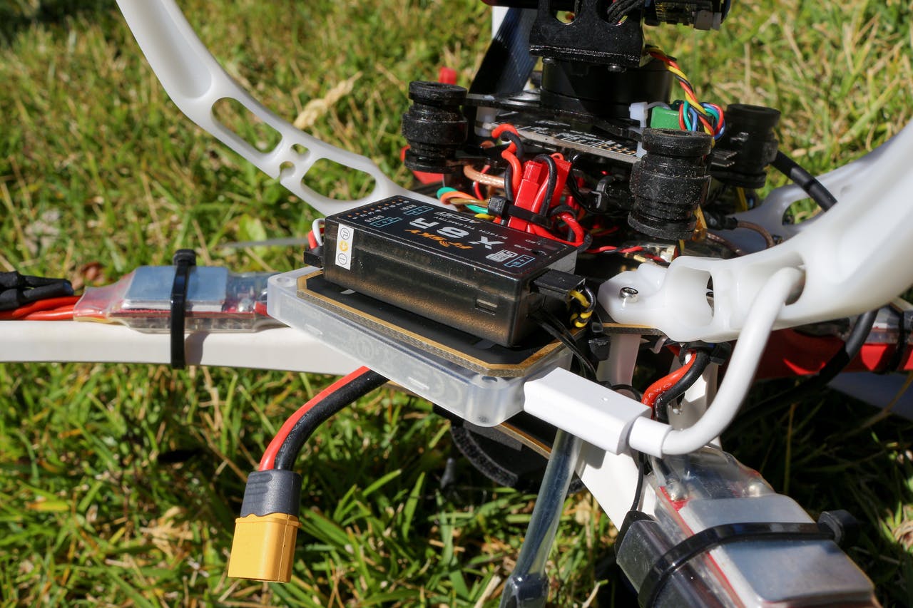
The RPI is mounted in the front part of the top side of the bottom plate, while the Coral TPU is on the back side:
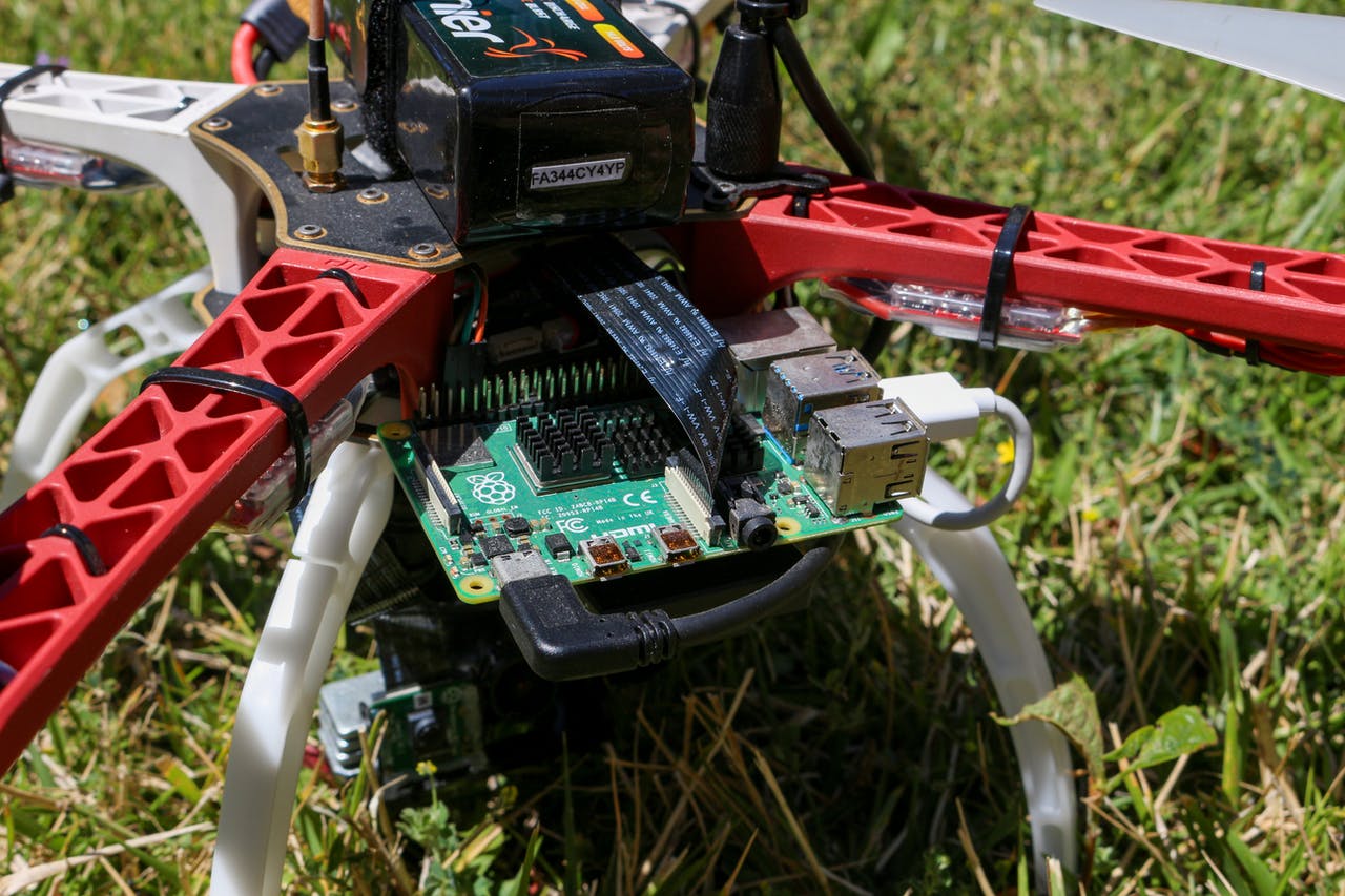
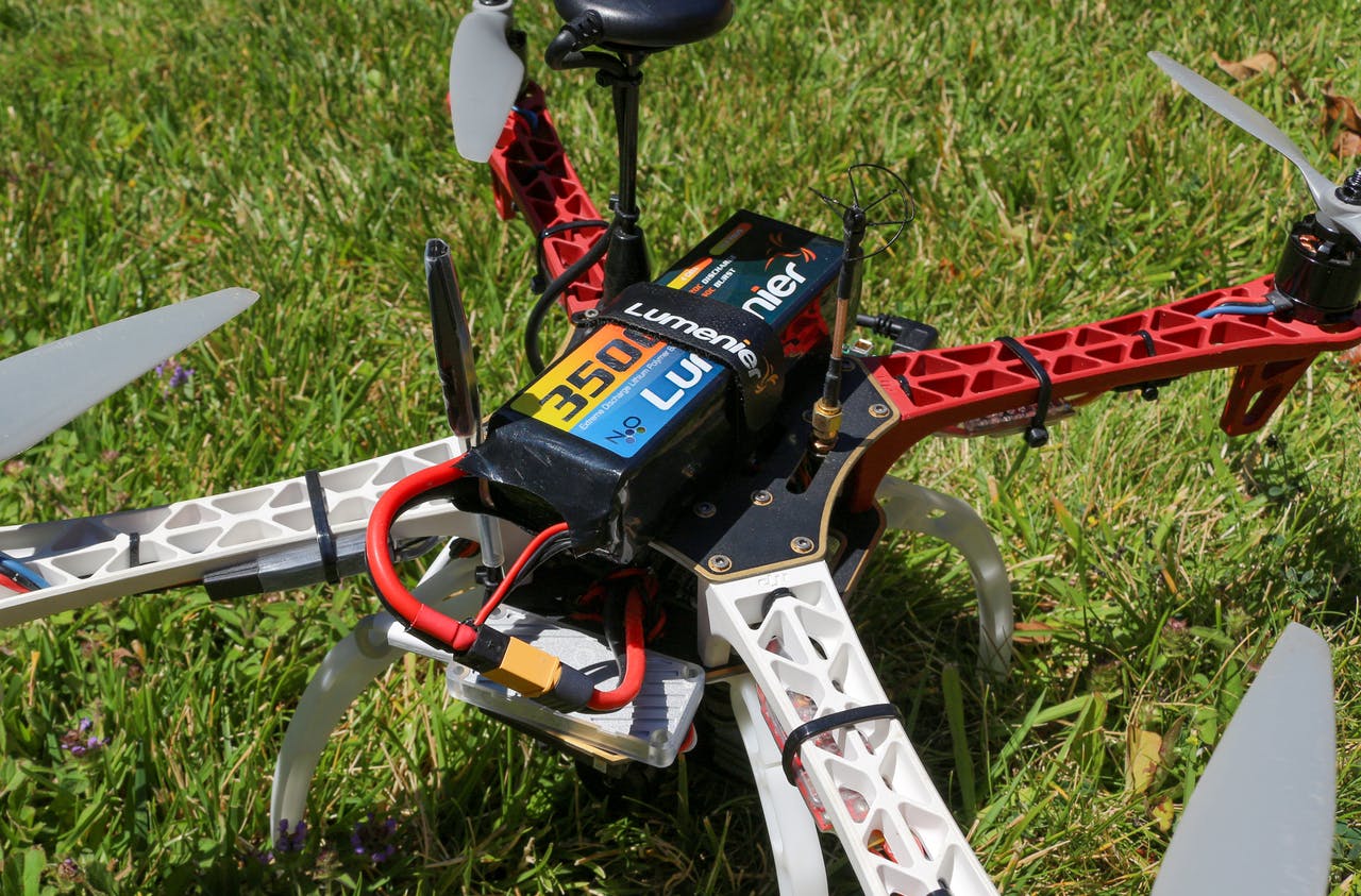
Make sure to plug in the USB-C cable for the Coral TPU into the RPI's blue USB 3 port
The GPS module and antennas are all mounted straight up and kept as far apart from each other to minimize interference:
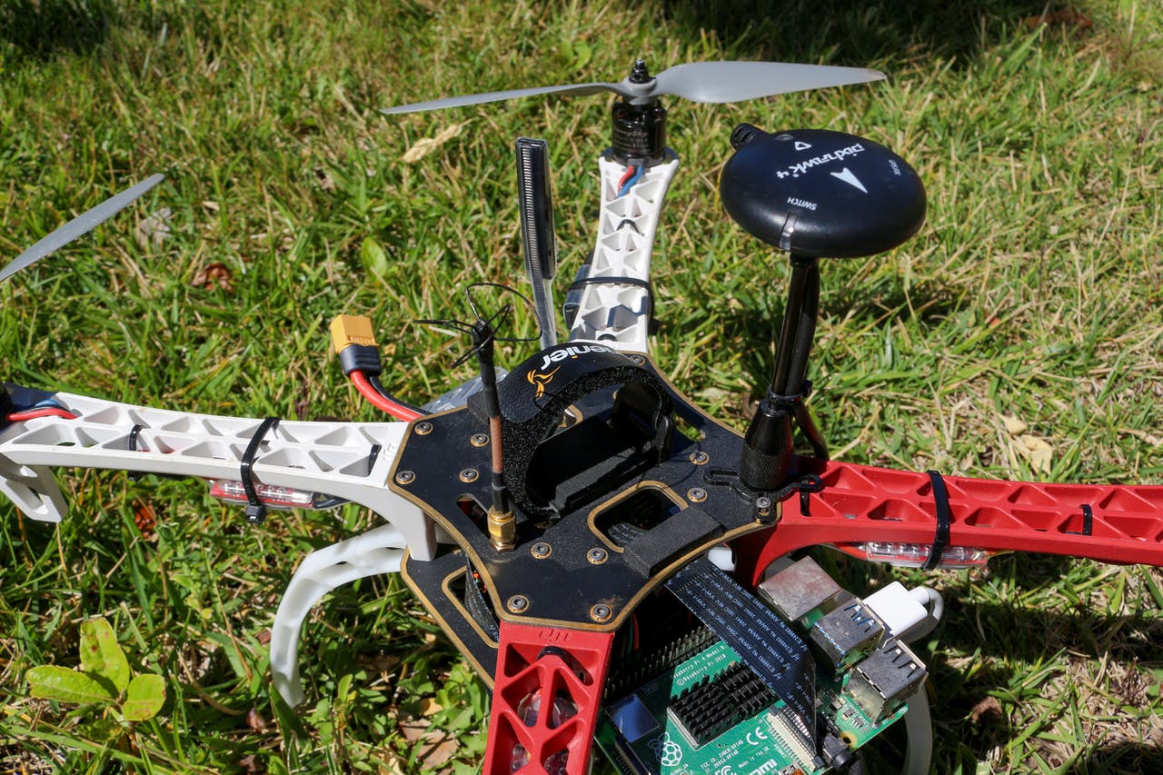
The battery strap and battery foam pads are also mounted on the top plate
Make sure that the arrow on the GPS module is aligned forward and aligned with the flight controller.
You will have to also modify a USB-C connector to power the RPI through your battery. This can be simply done by stripping off the cable of a USB-C cable and soldering the large red and black wires to the 5V UBEC. Connect the input power of the UBEC to the PDB (where the battery is connected) and the RPI will get power.
Connecting the camera setup for the FPV system is very simple. Simply solder the power lines of the VTX to the PDB and connect the camera to the VTX and antenna.
Next, we need to wire up the PixHawk 4 Flight Controller:
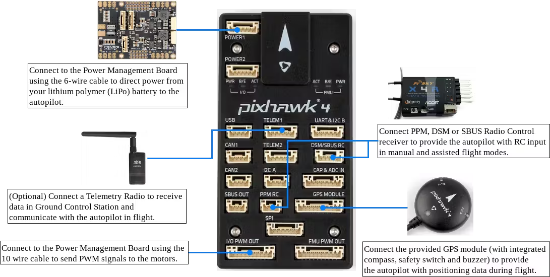
You can ignore the Telemetry Radio because its not needed as we will be using FrSky's Smart Port telemetry technology.
Connect the telemetry cable (linked in BOM) as shown:
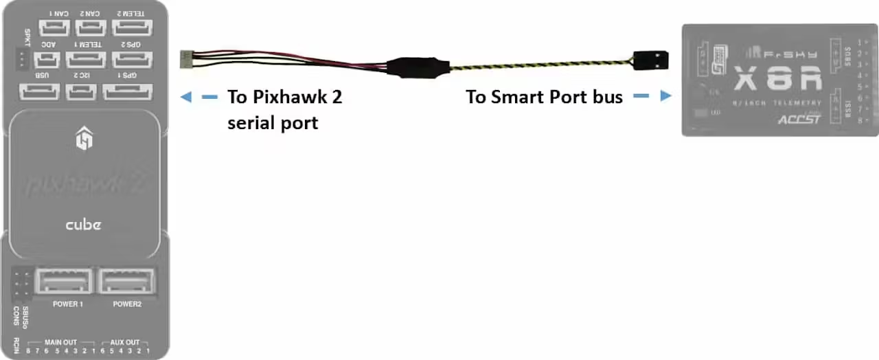
The cable connecting to the PixHawk 4 will be plugged into the UART & I2C B port.
Now, we need to wire up the gimbal to the flight controller so we can control the gimbal from the RPI and/or our radio transmitter. The gimbal linked above is pre-flashed with STorM32 so all we need to do is solder three wires to the gimbal:
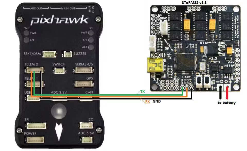
Instead of connecting it to TELEM 2, connect it to TELEM 1 because we will be using TELEM 2 to communicate with the RPI.
Last but not least, we can connect the RPI to the PixHawk 4 to allow the RPI to send commands to the flight controller via MavLink:
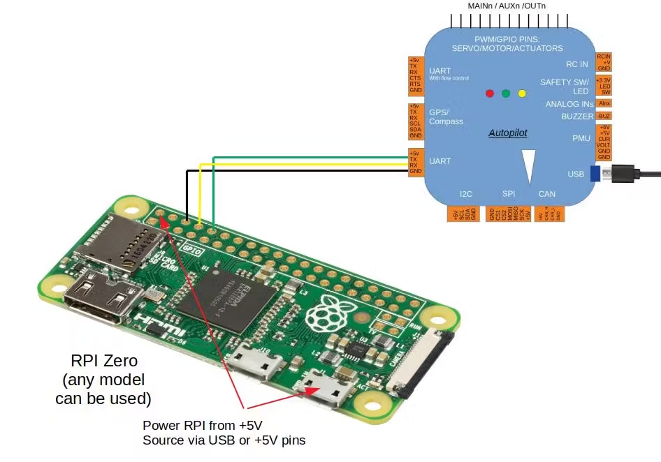
This illustration uses a RPI Zero, but the process is the same. Connect the flight controller’s TELEM 2 port to the RPI’s Ground, TX and RX pins. Here is the pin-out for the RPI 4 Model B (the image is a RPI 3 Model B+, but the pin-out is the same):
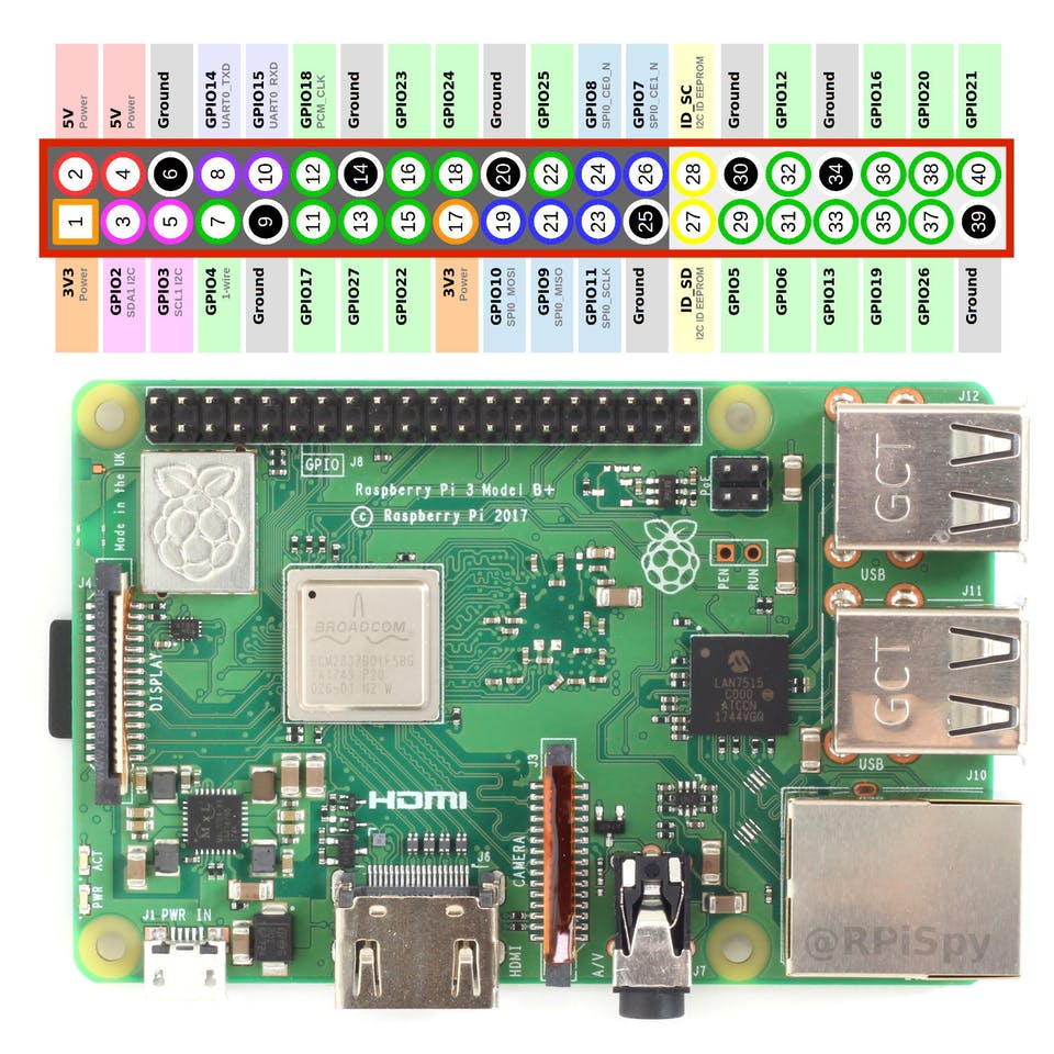
Pin 6 is ground, pin 8 is TX, and pin 10 is RX
It's important to realize that you connect the RPI's TX to the flight controller's RX and the RPI's RX to the flight controller's TX.
Adjusting The Gimbal Settings
While the gimbal linked in the project's BOM comes pre-flashed with STorM32 and is pre-calibrated, you sometimes have to adjust the trims if the gimbal is still not leveled. To test if you need to trim your gimbal, plug in your battery to power it. Make sure you boot it up on a level surface and keep it still until you here a beeping sound and the gimbal will initialize and try to remain at a stable position. If that stable position is not level with the horizon, then you need to trim the gimbal motors.
First, download the o323BGC firmware. This GUI will allow us to trim the gimbal. Its important that you download the zip file named: o323bgc-release-v090-v20160110:
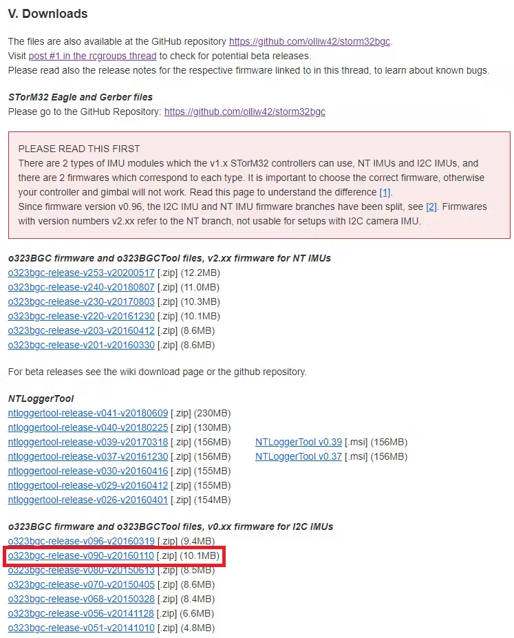
After downloading it, find it in your Downloads folder and double click on the zip file to open it. Double click on the folder named o323bgc-release-v090-v20160110 and then double click the Application file named o323BGCTool_v090. It will prompt you:
Click on the Extract all button and extract the files by selecting Extract in the second prompt. I chose the default location because I don't need to keep this application for long. If you do plan to use the GUI in the future, then it might be helpful to extract it in your Program Files folder.
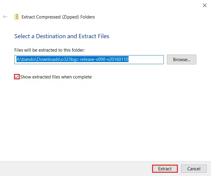
If you kept the Show extracted files when complete checked, it should automatically, open up the folder where it extracted all the files. Again, double click on the folder named o323bgc-release-v090-v20160110 and then double click the Application file named o323BGCTool_v090. This time it will open up the GUI application. You might get a Update prompt when opening it. Just ignore that message.
Next, plug in the gimbal to your computer via its Mini USB B connector.
Then, navigate to the lower left corner of the GUI to select the correct port. Mine was COM6:
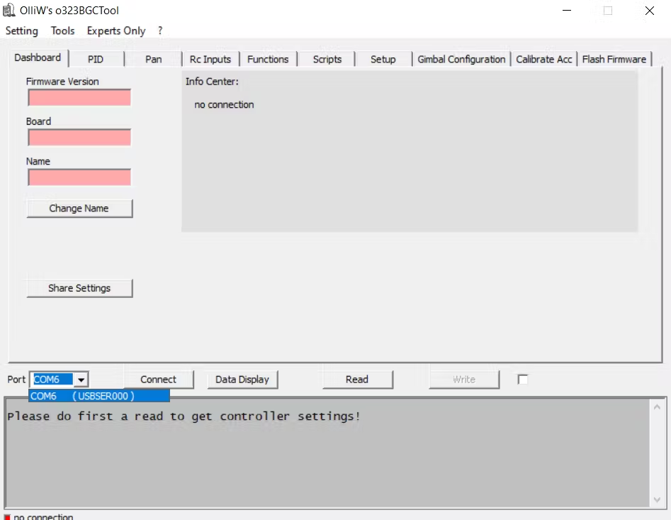
It may also be helpful to unplug any/all USB devices to avoid confusion between COM ports.
Now, click on the Connect button right next to Port drop down menu. It should read a bunch of information about the gimbal board and should look like this when complete:
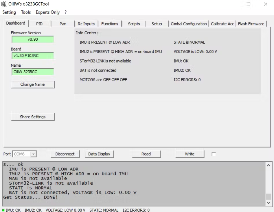
Navigate to the Rc Inputs tab:
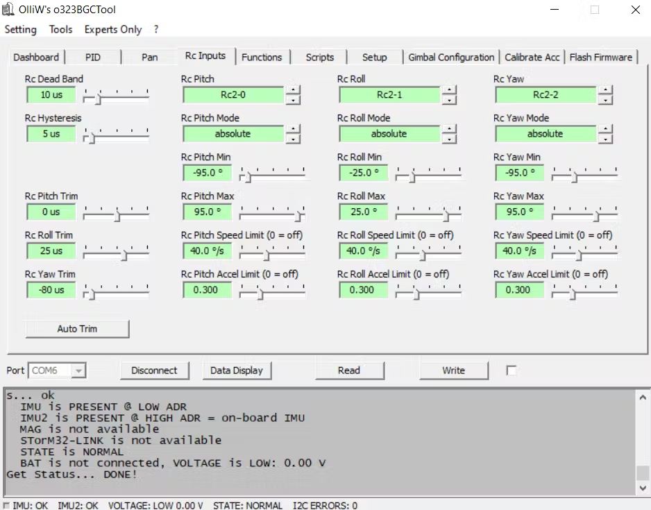
You will now see the option to adjust the trim. There is an option to Auto Trim, but I find it easier to manually do it.
First, you need to plug in the battery and wait for it to initialize (wait for the beeping sounds).
Then, you can adjust the trim in the GUI and click on the Write button to put the changes into affect. For reference, here is a good diagram to explain the differences between Pitch, Roll, and Yaw:
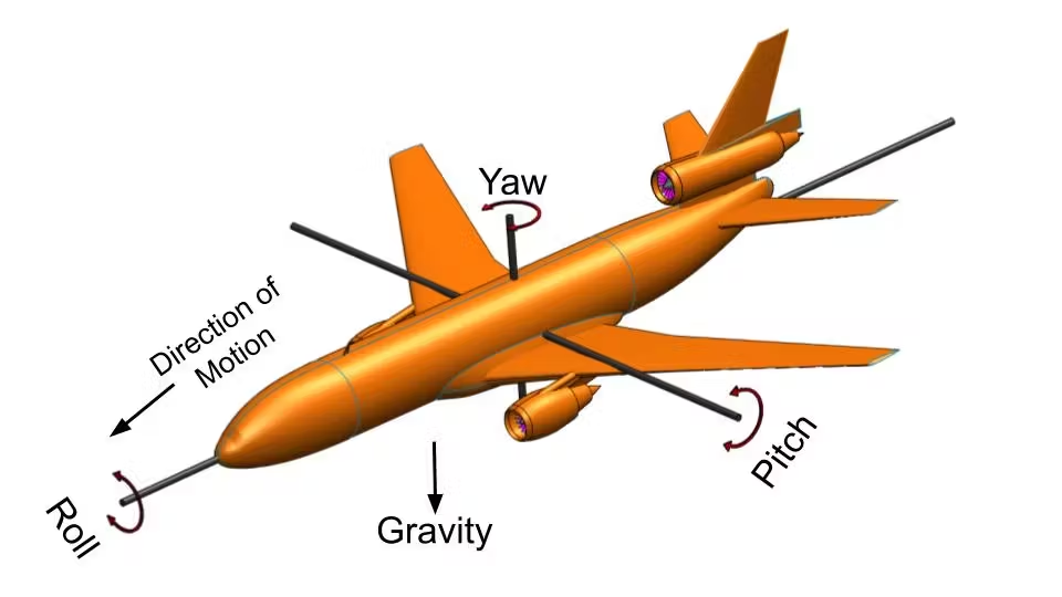
Once your gimbal is level with the horizon, click on the Disconnect button and unplug the USB cable.
Setting Up The Flight Controller
Setting up the PixHawk 4 is relatively simple. All you need to do is follow the First Time Setup guide. It will take you through installing Mission Planner (which you install on your laptop/PC), flashing new firmware, and configuration.
When configuring the flight modes, its important to at least have Stabilize, Guided, and RTL modes. Stabilize will be needed to take manual control of the aircraft, Guided is the mode which allows the RPI to take control over the copter, and RTL is just nice to have as a safety mechanism.
Once complete, take your drone on a test flight following the First Flight guide. Have fun flying your drone!
If everything works and you have a successful maiden, we can start setting up the flight controller to work with the RPI, gimbal, and Smart Port.
On Mission Planner, click to the CONFIG tab and navigate to the Full Parameter List section:
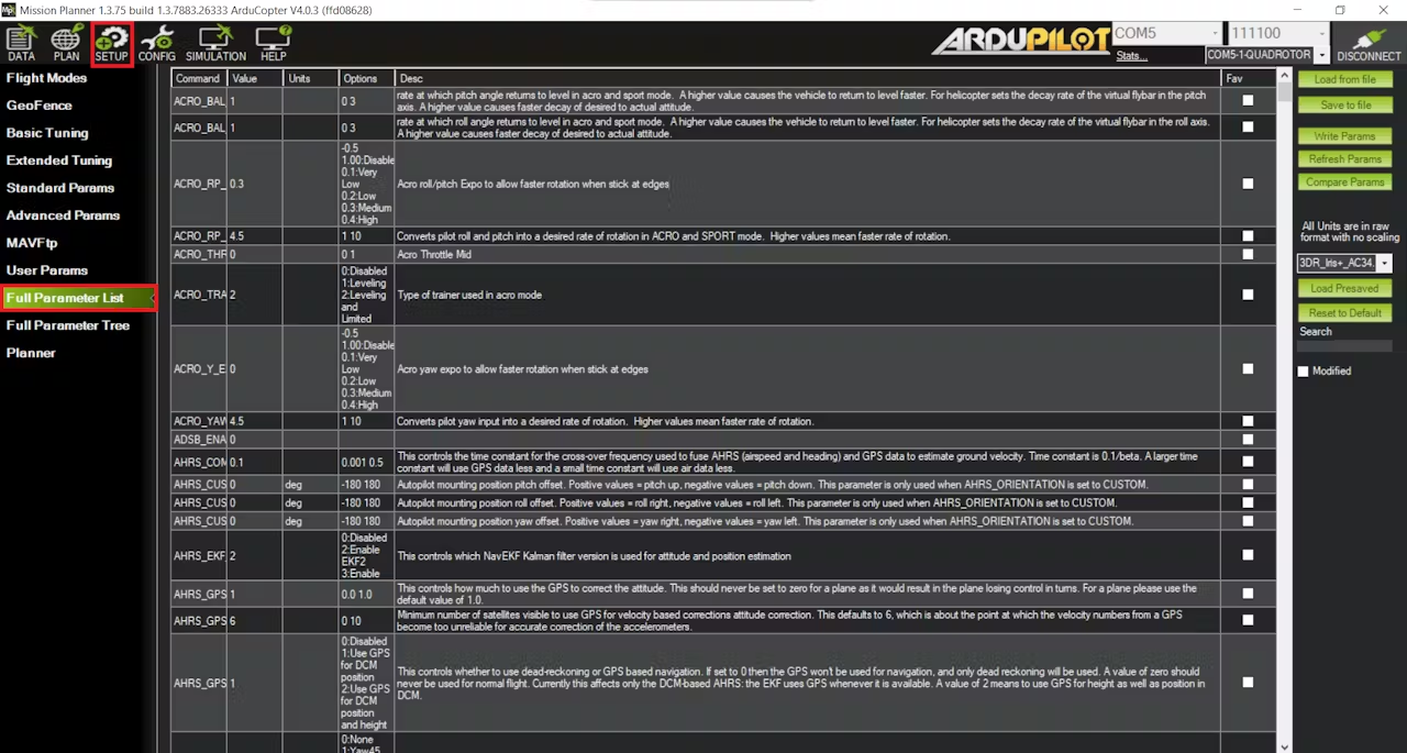
We will need to change the following settings:
- SERIAL2_PROTOCOL = 2
- SERIAL2_BAUD = 921
- SERIAL1_BAUD = 115
- SERIAL1_PROTOCOL = 8
- BRD_SER1_RTSCTS = 0
- MNT_RC_IN_TILT = 6 (This will allow you to control the gimbal's pitch via your Ch. 6 knob)
- Set MNT_TYPE = 5
- SERIAL4_PROTOCOL = 10
Instead of scrolling through all the parameter options, its very important that you use the Search feature located on the right side of Mission Planner:
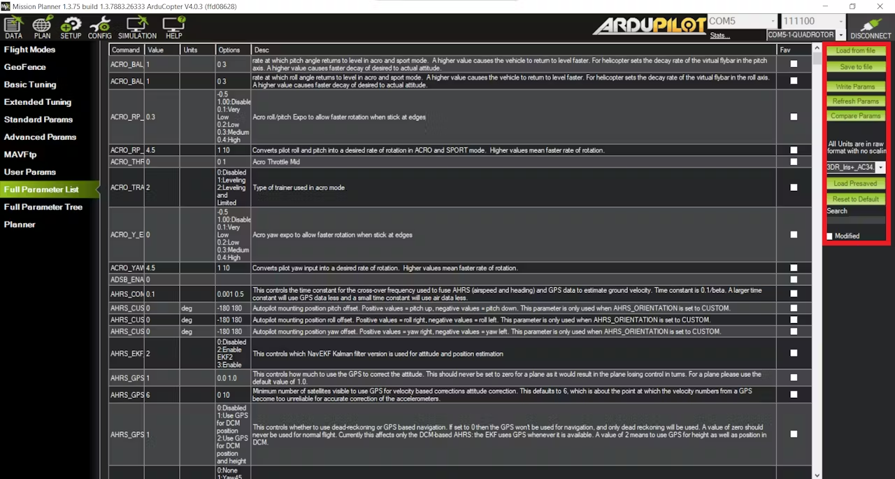
Once you have made the proper parameter changes, you can click on the Write Params button to apply the changes.
Setting Up The Telemetry
Now we can set up our radio controller to receive live telemetry data (Battery, GPS coordinates, etc.). This tutorial uses the Taranis X9D+, but any Taranis model will work.
First, make sure that your radio is bound to the drone's receiver. This process is simple. Simply create a new model on your radio and navigate to the Model Setup page. Scroll down to the Mode section and select D16. Then, scroll down to the Receiver No. section and click on the bind button. Now, locate the bind button on the drone's receiver. Hold down this button and then plug in the battery. Continue holding down this button until the light on the receiver turns green. Once this happens, you can click on the bind button on the transmitter to complete the binding process.
We can now install a lua script onto our transmitter that will organize all our telemetry data in a nice format:
The first step is to flash the radio with the latest OpenTX release.
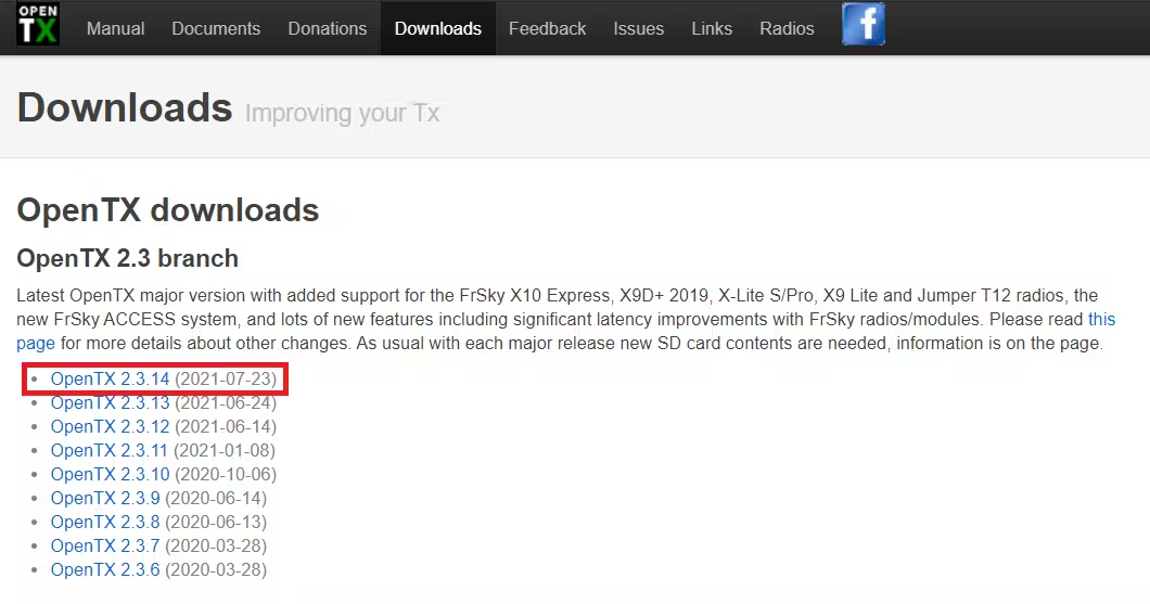
First, download the latest release of OpenTX companion. Go to the OpenTX Downloads page and select the latest release:
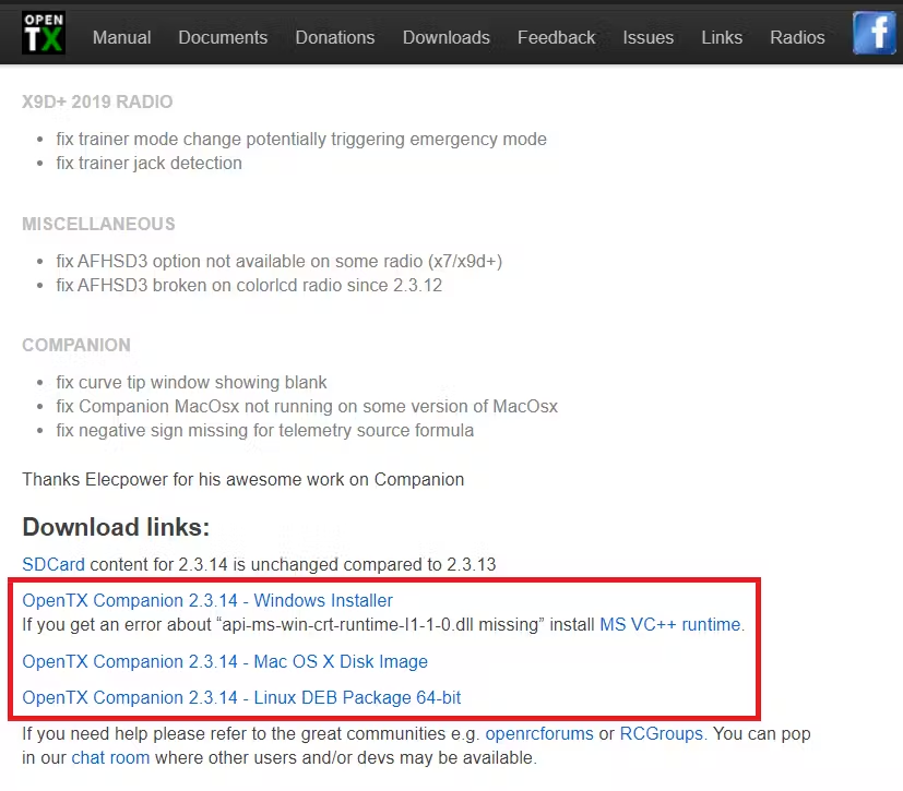
Scroll down to the Download links: section and download and install OpenTX Companion to your operating system:
Now, put your radio in Bootloader Mode by pressing both horizontal trim buttons inwards while powering it on:
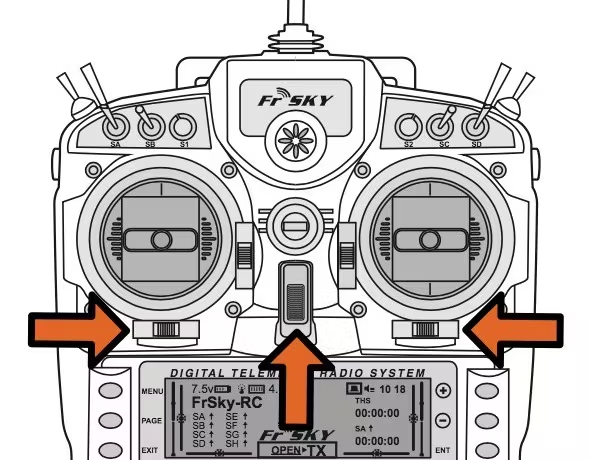
Now plug in a USB cable to the radio and connect it to your computer.
Open up your installed OpenTX Companion and click on the Settings button on the top row:

On the Radio Profile tab, select your Taranis model and select the noheli and lua checkboxes. Then select the Ok button to save your changes:
Next, click on the Downloads button:
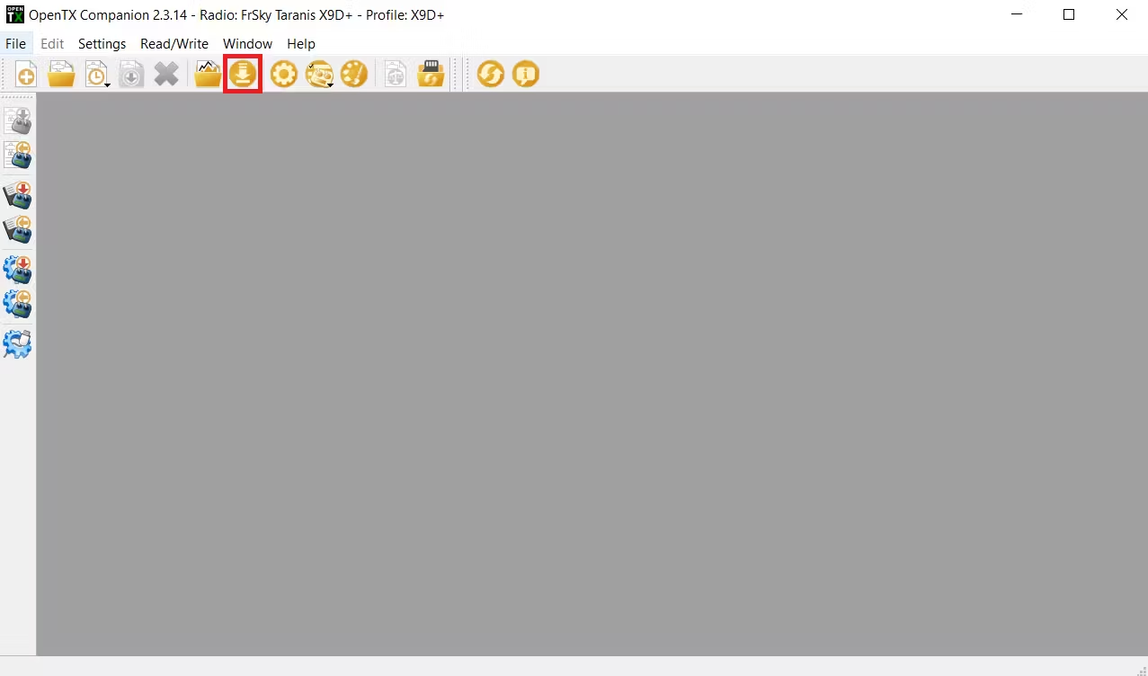
In the pop up window, click on the Download firmware button and save the .bin file:
Next, click on the Download SD contents button which will open a website where you can download the SD card content you need to copy to the SD card in your radio. Make sure to download the latest version:

Now, back up the SD card files on your computer first, then delete everything on it, and copy the new SD Card files onto it. Then copy any custom files you had previously from the IMAGES, SOUNDS, and MODELS folder.
Finally, we can flash the new firmware onto the radio. Click on the Write Firmware To Radio button on the left side menu and load the firmware file you saved previously. Then, click on the Write to TX button to flash the radio:
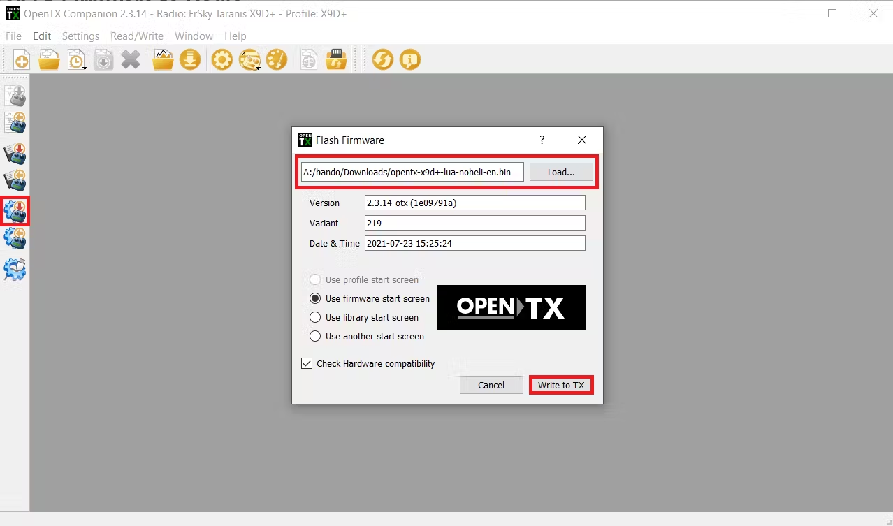
After flashing the radio, copy the contents in this folder to your radio SD card.
Turn on your radio and navigate to the Display page and assign yaapu9 to Screen 1 of type Script:
You can also create a separated telemetry page to display the GPS coordinates. Navigate to the Display page and assign the GPS telemetry variable to Screen 2 of type Nums:
Your second telemetry screen should now look like this:
Final Setup
Before we start flying this copter on search and rescue missions, we need to run a few test programs to ensure all the parts are working properly together.
First, we need to test the MavLink connection between the RPI and the flight controller.
On the RPI, run the connection_test.py program:
$ cd Search-and-Rescue-Drone
$ python connection_test.py
You should get a similar response:
Connecting to vehicle on: serial0
>>> APM:Copter V4.0 (d6053245)
>>> Frame: QUAD
>>> Calibrating barometer
>>> Initialising APM...
>>> barometer calibration complete
>>> GROUND START
Get some vehicle attribute values:
 GPS: GPSInfo:fix=3,num_sat=10
 Battery: Battery:voltage=16.787,current=0.0,level=100
 Last Heartbeat: 0.713999986649
 Is Armable?: True
 System status: STANDBY
 Mode: STABILIZE
Completed
Now that we can confirm that the RPI can communicate with the PixHawk 4, we can now test if the RPI and Coral TPU are working properly.
On the RPI, run the video_detect_test.py program:
$ python video_detect_test.py \
--model mobilenet_ssd_v2/mobilenet_ssd_v2_coco_quant_postprocess_edgetpu.tflite \
--labels mobilenet_ssd_v2/coco_labels.txt
If you have a monitor hooked up or using a VNC, you will see a pop up of the video feed from the RPI camera module. The result should look similar to the video in the Demo when you step in front of the camera.
Now that we can confirm that the RPI and Coral TPU are functioning accordingly, we can start to take the drone on some test flights. Our first test flight program will be takeoff_test.py. But first, we need to program the RPI to run the program on boot because we will no longer have SSH control on the field.
To do this, we need to edit the ~/.bashrc file again:
$ sudo nano ~/.bashrc
Navigate to the bottom of the file and add the following lines:
workon sar
python /home/pi/Search-and-Rescue-Drone/takeoff_test.py
Now, take your drone out to the field and perform the proper Pre-Arm Safety Checks. Once ready to arm, switch the drone into GUIDED mode. Shortly after, the drone should arm its self, take off to 10m, hover for 10 seconds, then land back down, and disarm.
Lets start moving the drone around using the square_movement_test.py program.
Just like before, edit the ~/.bashrc file:
$ sudo nano ~/.bashrc
Navigate to the bottom of the file, remove our previous addition, and replace it with the following lines:
workon sar
python /home/pi/Search-and-Rescue-Drone/square_movement_test.py
Now, take your drone out to the field and perform the proper Pre-Arm Safety Checks. Once ready to arm, switch the drone into GUIDED mode. Shortly after, the drone should arm its self, take off to 10m, then proceed to fly in a large square pattern, then land back down, and disarm.
We can now test to see if the drone is capable of recording footage, detect human subjects, and fly at the same time using the record_test.py program.
Just like before, edit the ~/.bashrc file:
$ sudo nano ~/.bashrc
Navigate to the bottom of the file, remove our previous addition, and replace it with the following lines:
workon sar
python /home/pi/Search-and-Rescue-Drone/record_test.py \
--model /home/pi/Search-and-Rescue-Drone/mobilenet_ssd_v2/mobilenet_ssd_v2_coco_quant_postprocess_edgetpu.tflite \
--labels /home/pi/Search-and-Rescue-Drone/mobilenet_ssd_v2/coco_labels.txt
Now, take your drone out to the field and perform the proper Pre-Arm Safety Checks. Once ready to arm, switch the drone into GUIDED mode. Shortly after, the drone should arm its self, take off to 6m, hover and record the camera footage. Make sure to stand in front of the drone's camera so that it can detect a human subject. After a couple seconds, you can switch the flight mode to RTL and it will land back to where it launched.
On the RPI, you will notice that there is a file in the Search-and-Rescue-Drone repository called: output.mp4. Open it and you will notice that its the recording. Make sure that the camera was able to detect you in the recording.
If the drone was able to pass all those tests, then you can finally put the drone into action. If you had any troubles, feel free to debug it yourself or ask for help in the comment section.
We can now edit the ~/.bashrc file for the last time:
$ sudo nano ~/.bashrc
Navigate to the bottom of the file, remove our previous addition, and replace it with the following lines:
workon sar
python /home/pi/Search-and-Rescue-Drone/main.py \
--model /home/pi/Search-and-Rescue-Drone/mobilenet_ssd_v2/mobilenet_ssd_v2_coco_quant_postprocess_edgetpu.tflite \
--labels /home/pi/Search-and-Rescue-Drone/mobilenet_ssd_v2/coco_labels.txt
Now, take your drone out to the field and perform the proper Pre-Arm Safety Checks. Once ready to arm, switch the drone into GUIDED mode. Shortly after, the drone should arm its self and begin searching for missing persons.